Bluetooth Low Energy
Information for this guide was taken from the following PDF.
Overview
- Uses frequency hopping transceiver to combat interference
- Data Rate = 1Mb/s
- Multiple Access Schemes Used
- FDMA (Frequency Division Multiple Access)
- TDMA (Time Division Multiple Access)
- Channels
- 40 - 2MHz channels (3 advertising, 37 data)
- f = 2402+2k MHz (k=0,...,39)
Transmitter Specifications
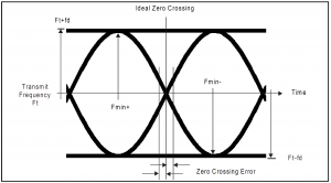
Modulation Characteristics

- GFSK (Gaussian Frequency Shift Keying)
- Bandwidth-Bit Period Product = 0.5
- Modulation Index 0.45 to 0.55
- ‘1’ = Positive Frequency Shift
- ‘0’ = Negative Frequency Shift
- Symbol Timing < <math>\pm</math> 50ppm
- Minimum Frequency Deviation > 185kHz
Frequency Tolerance
- Initial Center Frequency <math> \pm </math> 150 kHz
- Maximum Drift (during packet) <math> \pm </math> 50 kHz
- Maximum Drift Rate 400 Hz/us
Spectral Mask

| Frequency Offset | Spurious Power |
|---|---|
| 2 MHz (|M-N| = 2) | -20 dBm |
| 3 MHz (|M-N|<math>\geq</math>3) | -30 dBm |
Receiver Specifications
Actual Sensitivity Level
- Defined as the receiver input level for which a BER (bit error ratio) of 0.1% is achieved
- < -70 dBm (from any transmitter that meets specifications)
Interference Performance
- Measured with a wanted signal 3dB over the reference sensitivity level
- Measurement resolution is 1MHz
- BER should be < 0.1% for all ratios listed in the table
| Frequency of Interference | Ratio |
|---|---|
| Co-Channel Interference | 21 dB |
| Adjacent (1 MHz) Interference | 15 dB |
| Adjacent (2 MHz) Interference | -17 dB |
| Adjacent (<math>\geq</math>3 MHz) Interference | -27 dB |
| Image Frequency Interference | -9 dB |
| Adjacent (1 MHz) Interference to In-Band Image Frequency | -15 dB |
- 5 Spurious Response RF Channels (that don't meet the requirements) are allowed <math>\geq</math>2 MHz from the wanted signal (excluding the image frequency and image frequency <math>\pm</math>1 MHz. On these spurious response RF channels, a relaxed interference requirement of -17dB shall be met.
Out-of-Band Blocking
- Measured with a wanted signal 3dB over the reference sensitivity level
- Interfering signal shall be a continuous wave signal
- Desired signal has be a reference signal (defined below)
- BER should be < 0.1%
| Interfering Signal Frequency | Interfering Signal Power Level | Measurement Resolution |
|---|---|---|
| 30 - 2000 MHz | -30 dBm | 10 MHz |
| 2003 - 2399 MHz | -35 dBm | 3 MHz |
| 2484 - 2997 MHz | -35 dBm | 3 MHz |
| 3 - 12.75 GHz | -30 dBm | 25 MHz |
- Up to 10 exceptions are permitted (which are depending on the given RF channel and are centered at a frequency which is an integer multiple of 1 MHz)
- For at least 7 of these spurious response frequencies, a reduced interference level of at least -50dBm is allowed
- for a maximum of 3 of these spurious response frequencies, the interference level may be lower
Intermodulation Characteristics
A BER <math>\leq</math>0.1% shall be met under the following conditions
- The wanted signal (at frequency = <math>f_0</math>) has a power level 6 dB over the reference sensitivity level. The wanted signal shall be the reference signal (defined below)
- A static sine wave signal (at frequency = <math>f_1</math>) has a power level of -50 dBm
- An interfering signal (at frequency <math>f_2</math>) has a power level of -50 dBm. The interfering signal shall be the reference signal (defined below).
<math>f_0 = 2f_1 - f_2 \,</math>
<math>|f_2-f_1|=n \, </math> where n=3,4,or 5
Maximum Usable Level
- Must be greater than -10dBm with BER < 0.1%
Reference Signal
- Modulation = GFSK
- Modulation Index = 0.5 <math>\pm</math>1%
- BT = 0.5 <math>\pm</math>1%
- Bit Rate = 1 Mbps <math>\pm</math>1ppm
- Modulating Data for Wanted Signal = PRBS9
- Modulating Data for Interfering Signal = PRBS15
- Frequency Accuracy Better than <math>\pm</math>1ppm