Mixed Signal Simulation
Mixed Signal Simulation combines a SPICE based simulator, such as Spectre, with an HDL simulator, such as ncverilog. This allows you to simulate analog and digital functionality together, without wasting computing resources solving all of the precise voltages within the digital portion. There are a few different ways to do this, and the basics of each of them are listed below.
Cadence AMS
This simulator simply combines spectre and ncsim. As long as it's set up right, it works just like you'd expect! In your .cshrc add
setenv AMSHOME /usr/caen/incisiv-12.20.012
set path=($path $AMSHOME/tools/bin)
You can find general documentation on the simulator at $AMSHOME/doc/amssimug/amssimug.pdf
As with any simulation, to run a mixed signal sim you need to create a test bench. In this case, it can either be a schematic or a verilog test bench. In this example, a schematic will be used. Here the test bench contains two analog inverters, made from transistors, as well as a verilog inverter.

The verilog inverter, 'invd' is simply defined by the verilog statement assign z=!a;. The verilog description of a cell is generally stored in the 'functional' cell view.
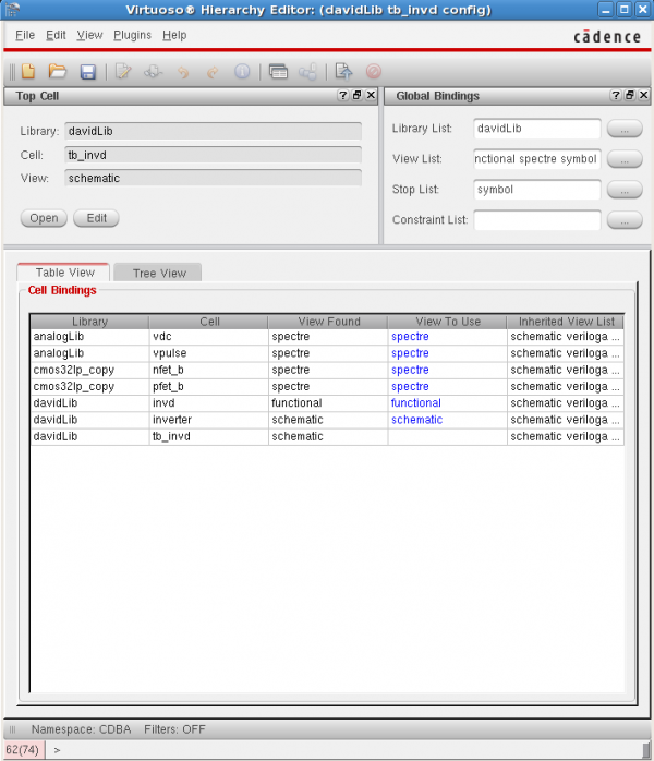
The first step to doing a mixed signal simulation is creating a 'config' view for whichever cell you're simulating (ie. your test bench). In the library manager, choose File->New->Cell View, then change the type to 'config' and create the view. This opens the hierarchy editor. This configuration tells the simulator which view to use for each cell, effectively dictating which cells are analog and which are digital. Make sure the view list and stop list are populated with the types of views you want the hierarchy editor to find for you simulation. Then look in the "cell bindings" section. This shows which view is used for which cell. You can look at which views the tool found, and you can use the "View To Use" field to explicitly decide which view is used for a cell, if desired.

Once you've created the config view in order to specify which components use the Spectre simulator and which use verilog (functional) views, you can set up the simulation. Click "Open" under the "Top Cell" section of the config view in order to open the test bench schematic again. Now launch ADE(Note: AMS might not work correctly if you don't open the schematic from the config view, for whatever reason). In the ADE window, choose Setup->Simulator/Directory/Host and chose "ams" as the simulator. Now set up the models as usual. You can also set up various other normal Spectre options. However, there are still some important AMS specific things to set up.
First, under Simulation->Solver, make sure you're using Spectre (unless you want to use ultrasim for some reason). Also, under Simulation->Options->AMS Simulator, there are an abundance of options to look at. I've found that I avoid issues by selecting "Compile digital Verilog without -ams option" and "Enable line debug to use with SimVision". Also, under the SDF tab, you can specify an SDF file with timing information to be used for simulation.
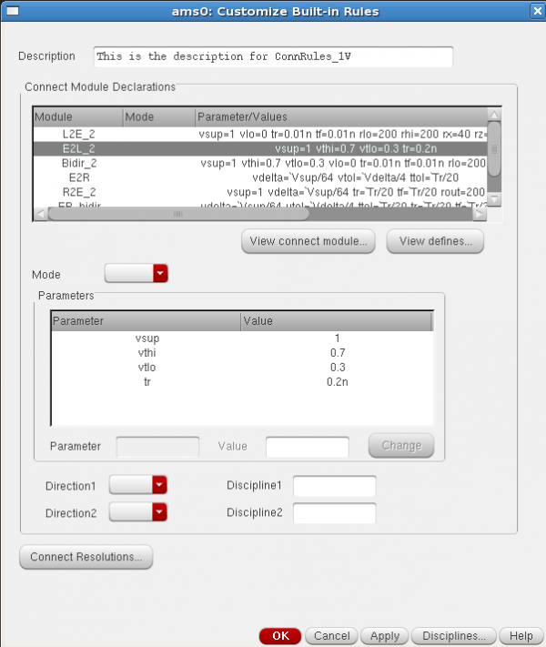
Finally, we must define how the analog and digital portions of the design connect to each other. Go to Setup->Connect Rules. Essentially, this page defines elements which are inserted at the boundaries of verilog and analog blocks to convert voltages to binary values and vice versa. The easiest way to specify this is by modifying built in rules. Under "Built-in and Customized rules", select Rules Name "connectLib.ConnRules_18V_full_fast", which is a set of connection rules for 1.8V logic. Click customize, then go through each of the modules, scaling the values appropriately to whatever VDD you are using. If using multiple supplies... good luck. There's some information on that in the document referenced above.

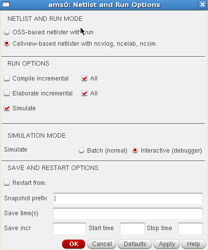
Make sure the correct connection rules are enabled, and click OK. Set up whatever analysis you want to do, like you would in spectre. Note that the options are limited - the mixed signal simulator is obviously mostly used for transient simulations. Before you run, choose Simulation->Netlist and Run Options. Here there are a last couple of options on how to run the sim. The top two sections shouldn't really matter, but we had the most success when it was configured as shown below.

Under "SIMULATION MODE", you can choose "Batch" or "Interactive". In Batch mode, the simulation runs exactly as it normally does when running spectre sims, letting you view data in the ADE Waveform Viewer. On the Other hand Interactive mode launches SimVision, allowing you to step through the simulation one step at a time, as well as setting breakpoints in your verilog, much like a normal verilog simulator. You can potentially get issues with stepping through veriloga code, however. Nevertheless, it's nice to be able to see how your simulation is progressing in real time, so it's worth a look.
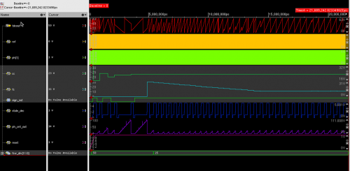
After this is all setup, go ahead an run your simultion! Hopefully it works, and you get something like the results below, from my PLL:

If you have any questions about this, ask David Moore (mooredav).
BDA AFS
Flynn's group has used this. Doesn't work with ST28's weird transistor models, but should work for other kits and is faster. Ask Jeff or Nick.
Questa AMS
This is just listed here for completeness. It uses the Mentor Graphics simulators, which don't integrate quite as well with Cadence, but it's an option. In your .cshrc add
setenv MGC_AMS_HOME /usr/caen/mentor-ams-12.2a
set path=($path $MGC_AMS_HOME/bin)
If you want to try using this, ask David Moore (mooredav).